Mechanics Development for Hobbyists and Students of Robotics
Mechanical Engineering applies the principles of physics and materials science for the design, manufacture, and maintenance of mechanical systems. These systems assist industries such as aeronautics, heating and cooling, and manufacturing. The primary focus is on mechanics, kinematics, thermodynamics, structural analysis, and materials science.
This page is intended to provide pointers to software and tools that can help with the engineering of mechanical devices. Any software referenced here is either free, inexpensive, or demo software so it can be tried without initially investing significant money. Where possible we've included a link to the site where you can get the latest version rather than a direct download of a possibly stale version.
Some basic mechanical components used in rovers or spacecraft are wheels, robotic arms, and drills or grinders. Software tools that allow you to draw a mechanical device you're creating would allow you to visualize and debug the mechanics before building it. A common example of this type of application is CAD (Computer Aided Design). CAD software can generally be categorized as either surface modeling, which can be 2D or 3D, or solid modeling, which is always 3D. If these software models are 3D and can be exported to *.stl files (Stereolithography file format) they can further be turned into physical models by rapid prototyping with additive 3D printing or into working devices with subtractive CNC milling.

common mechanical items you might need to design
Primary Structures
A primary structures (also called a frame or chassis) holds functional components in place to enable their physical and electrical connections. The primary structure for a CubeSat is typically a commercial-off-the-shelf (COTS) structure or a custom structure that is either machined or printed. COTS CubeSat structures can simplify development, but only if the complexity of the mission, subsystems, and payload requirements are within the designed capabilities of the particular COTS structure. Custom machined structures enable greater flexibility in mission specific system and payload design. The typical commercially available CubeSat structure has been designed for low-Earth orbit applications and limited mission durations, where shielding requirements are confined to limited radiation protection from the Van Allen Belts. Further, commercially available CubeSat structures are designed for satellites; they won't have capabilities for implementing a lander nor rover nor terrarium. There are now several companies that provide CubeSat structures. Most CubeSats are machined from 6061 or 7075 aluminum and are designed with several mounting locations for components in an attempt to offer configuration flexibility for spacecraft designers. For COTS Cubesat structures, 1U, 3U, and 6U frames or chassis are the most common.
- Pumpkin, Inc.
- AAC-Clyde
- NanoAvionics
- Radius Space
- Innovative Solutions In Space (ISIS)
- GOMspace
- EnduroSat
- Complex Systems & Small Satellites (C3S)
- InterOrbital
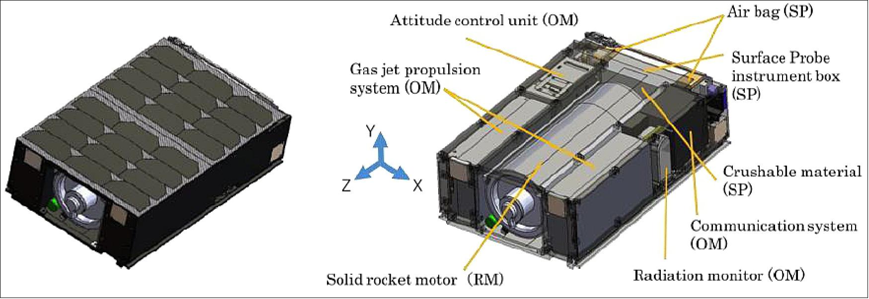
6U CubeSat based OMOTENASHI Lunar spacecraft with components held by structure
Gears
Gears are used to transfer motion and torque between mechanical components in mechanisms.
While low Earth orbit CubeSats don't use many gears, things with regularly moving mechanisms such as rovers, arms, and manipulators do.
Some common types of gearing systems include:
spur gear,
planetary gears,
bevel gear,
worm gear, and
rack and pinion gears.
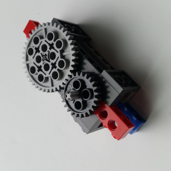
spur gear
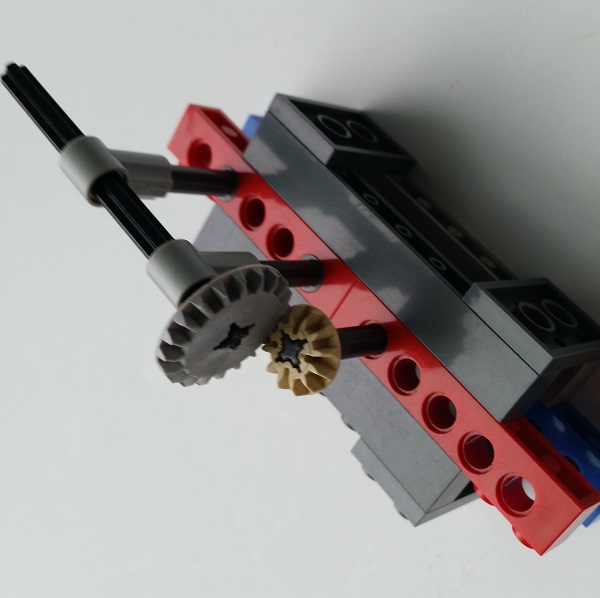
bevel gear
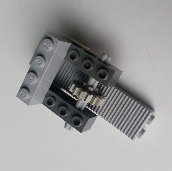
rack and pinion
Deployable Booms
A deployable boom is a mechanical item that is rolled up or folded for stowage and deploys using a spring mechanism. They are typically used for a one time deployment of antennas, solar panels, or instruments.
Robotic Arms
Some categories of robotic arms include:
rectangular coordinate,
cylindrical coordinate,
spherical coordinate,
revolute, and
scara.
Arms on Surveyor and Viking landers would be categorized as spherical.
The Surveyor landers that carried a soil mechanics surface sampler (SMSS) used a scissors telescoping mechanism.
The Viking landers extendable arm used a creative design involving two curved metal strips like two carpenter's tape measures welded together top to bottom forming a tube.
The arm was flattened, rolled, and stored in a drum until unrolled for deployment.
Autonomous rovers have also used robotic arms on Mars.
These include Sojourner, the MERs Spirit and Opportunity, Curiosity, and Perseverance.
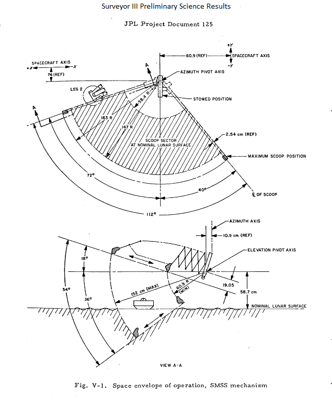
Surveyor soil mechanics surface sampler range of motion
Environment Manipulators (scoops, drills, or grinders)
An environment manipulator is a tool or instrument designed to manipulate the environment outside of a spacecraft lander or rover on a celestial body. For the US Apollo program to the Moon the astronauts used a number or environment manipulators that they brought to the Moon in the Lunar Module. Apollo Lunar Surface Drill was used to obtain a continuous soil column up to 3 meters in length and to provide holes for the placement of heat flow probes. The drill bit had 5 tungsten-carbide tips and was 6.0 cm long.
Some NASA Surveyor landers and both NASA Viking landers had soil manipulators on the end of their arms.
NASA Mars Exploration Rovers Spirit and Opportunity each had a Rock Abrasion Tool (RAT) that was used to grind or brush off rocks.
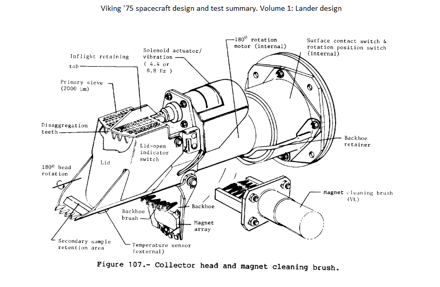
Viking soil collector mechanics
CAD
- Link to OpenSCAD for 32-bit Windows (should work on 64-bit Windows)
- Link to Sketchup for 32-bit Windows (should work on 64-bit Windows)
- Link to Gmsh for Windows
- Link to QCAD for Windows, Linux, or Mac
STL Viewers
The stereolithography or STL file format is often used for designs to be sent to 3D printers. The STL file is typically processed by slicer programs such as Slic3r to generate G-Code files which are accepted by most 3D printers. The G-Code or RS-274 file format is often used for numerical control (NC) of automated machine tools which includes 3D printers for additive manufacturing as well as CNC milling machines for subtractive manufacturing.
- Link to Fast STL Viewer for Android smartphones and tablets
- Link to GLC Player for Windows and Mac OS X
- Link to 3D-Tool Free Viewer for Windows
- Link to Materialise MiniMagics for Windows
- Link to ADA 3D STL Viewer for Windows
- Link to Open 3D Model Viewer for Windows
- Link to EasyViewStl for Windows
- Link to STLView for Windows
- Link to STLView for Android smartphones and tablets
Other links
- Link to RepRap (3D printers)
- Link to 3D CAD Models Engineering for Android smartphones and tablets
Text Copyright (C) 2017 - 2023 R. J. Kuhn. Please note that you are not allowed to reproduce or rehost this page without written permission.

